Yes, ProLink can monitor multiple components. You can define multiple measurement jobs, which will be measured
sequentially. Each job can monitor a different component with its own configuration. As long as ProLink can “see” the
vibration of the component with its vibration sensor, it can monitor it. For example, if you have a machine with
multiple bearings, you can place the sensor on the housing and configure multiple jobs to monitor each bearing
individually.
There is no fixed limit on the number of configurations or components that ProLink can monitor. However, we advise to
keep the number of configurations reasonable, say 5-10 per sensor position, since each configuration adds complexity to
the setup and maintenance of the system. Also, the more configurations you have, the longer it will take for ProLink to
cycle through all the measurements, which might affect the timeliness of the data.
How can I analyze data with ProLink?
The are several ways to analyze data with ProLink:
Check the measurement data in the web interface of ProLink. Here you can view the trends of all measured
characteristic values. There is also a basic viewer in which you can view the time signals, both in the time
domain and as spectrum. This view offers some basic tools like a cursor to measure times and frequencies, and the
possibility to show the damage frequencies of components defined for the measurement configurations, like bearings.
Use the viewer in the SmartUtility software. This can also show trends and time signals, but offers more tools for
analyzing the data, e.g. multiple cursors or a waterfall plot.
Use the ExpertViewer software. This offers the same functions as the SmartUtility viewer.
How can I monitor a machine with a dynamically changing speed?
With ProLink, it is possible to monitor machines that operate at dynamically varying speeds. To effectively monitor
such machines, you need to set up the following:
a digital (pulsed) speed signal, preferably with multiple pulses per revolution, e.g. from an encoder disk
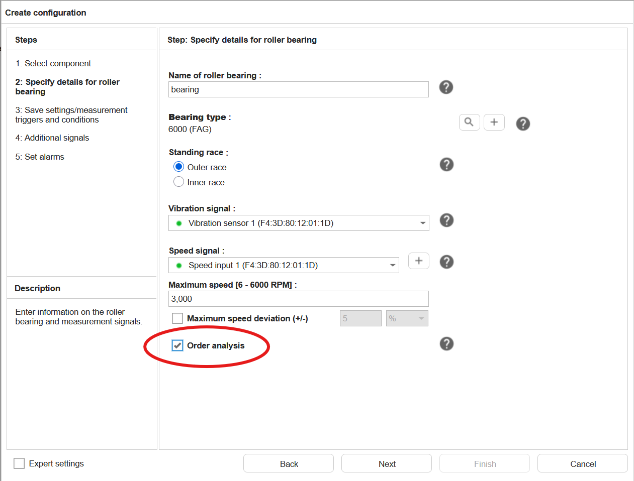
measurement jobs that use order analysis as the measurement method. This method allows you to analyze vibration data
in relation to the rotational speed of the machine, making it ideal for machines with variable speeds
Beware that the order analysis checkbox is disabled when the selected speed input is not suitable for order analysis,
i.e. when no digital pulse input is selected.
How can I monitor machines with variable speed or load?
Monitoring machines with variable speed or load can be challenging, as traditional vibration analysis methods often rely
on constant operating conditions. However, in ProLink you can use several mechanisms to effectively monitor such
machines:
Most measurement templates use speed dependent KPIs. For this a speed input has to be used. The speed can be provided
by a tachometer input (pulses), from an analogue speed input or from an external source like a fieldbus.
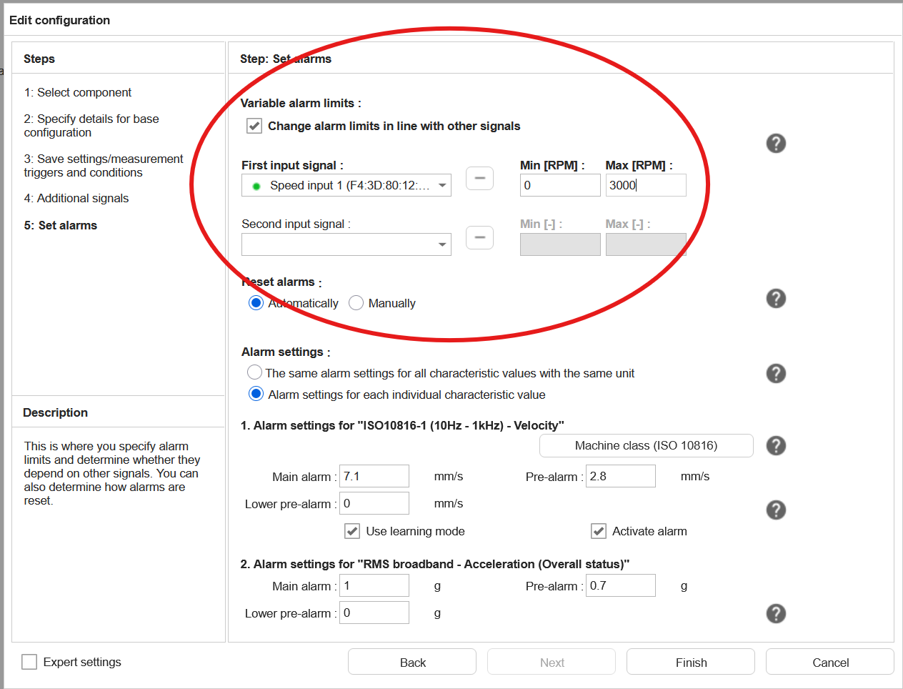
A machine running at a higher speed or a higher load will usually have higher vibration levels. For this reason, the
alarm levels should be adapted to the current operating conditions. In ProLink this can be done by using alarm maps.
These can be configured in the measurement job configuration wizard in the “Set alarms” step.
More information about configuring speed dependent alarm limits can be found in the
manual
How can the ProLink use a speed signal for its measurement jobs?
There are several ways to provide a speed signal to ProLink for its measurement jobs:
When you know the speed of the machine, you can enter it manually in the input configuration as an “Input with a
fixed value”. In the measurement jobs, this can then be used as any other speed input. Should the speed of the machine
change (e.g. when there is a change in the setup of the machine), you can edit this fixed speed input value
accordingly.
Use a digital input when you have a pulse signal from a sensor like a tacho probe, e.g. one pulse per revolution or
multiple pulses per revolution with a pulse wheel.
Use an analogue input when you have a 4-20mA or 0-10V signal representing the speed of the machine, originating from
an analogue speed sensor or an analogue output from a PLC.
Use a communication channel when the speed is provided by a PLC or another device via a network like SLMP, OPC/UA or
PROFINET.
When you have multiple speeds depending on each other, e.g. in gearboxes or belt drives, you can add scaling factors to
a speed input, directly in the input configuration. This way you can calculate the speed of a shaft based on the speed
of another signal. These scaling factors can be used in the measurement configurations as if they were real speed inputs.
How can the alarm status of ProLink be signaled?
The alarm status of ProLink can be signaled in different ways:
via the digital outputs of the device. These can be configured to signal the pre-alarm and/or main alarm status.
via the status-LED on the front panel
an email notification can be triggered
it can be signaled via a communication channel, like SLMP, OPC/UA, PROFINET or EtherNet/IP
How does the learning mode work and which settings should I choose?
When a new measurement job is configured, default alarm limits are set. With the learning mode, the device can
automatically set the alarm limits for the current measuring point and the current state of the machine. With the
default settings for the learning mode, this will get good results for most cases.
What the learning mode does, after it is started for the measurement job, or for the entire device, is to collect trend
values for each of the KPIs in the measurement job. By default, it needs 1000 values for this. When this number is
reached, from these 1000 values a kind of average value is calculated, i.e. the normal value of the KPI in the current
state of the machine. The alarm limits are then changed to be a bit higher than this value. By default, the pre-alarm is
set to this value times two, the main alarm limit to this value times three.
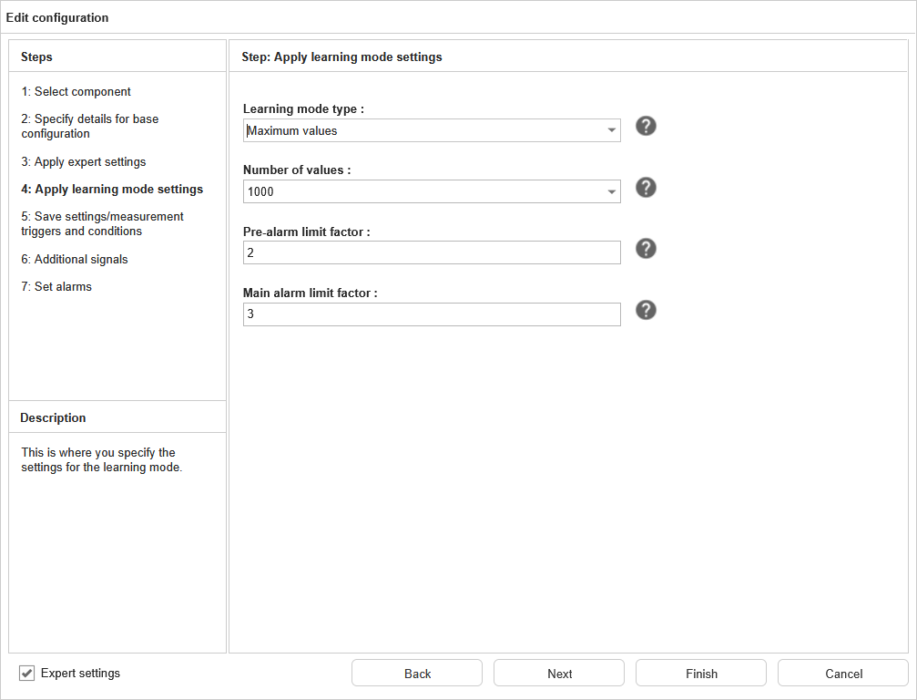
It is possible for the user to change the settings for the learning mode. To do this, open the wizard for the
measurement job, enable the expert settings and navigate to the fourth step. This shows the following settings:
Here you can change the following:
Setting
Explanation
Learing mode type
Here two algorithms can be selected to get the above mentioned average value. “Maximum values” is the best setting for most cases, as it will search for the maximum values in the trend. When the trend is not so stable, “Standard deviation” might give better results.
Number of values
Defines how many trend points are used to calculate the average. Lower values will learn faster, but might have a higher risk of not catching all states of the machine, setting the alarm limits too high or too low.
Pre-alarm limit factor
This is the factor with which the average value is multiplied to get the pre-alarm limit. The default value of 2 means that the pre-alarm will be set at twice the average value.
Main alarm limit factor
This is the factor with which the average value is multiplied to get the main alarm limit. The default value of 3 means that the main alarm will be set at three times the average value.
See the manual for more information on the learning mode.
How long does it take ProLink to measure a measurement job?
The measurement time of a measurement job depends on several factors. In general, each recorded time signal has a
duration which is defined by the following settings:
Lowpass filter (e.g. 1kHz, 5kHz, 10kHz, …): The higher the lowpass filter, the faster the signal is sampled and
thus the faster the measurement is completed. The sampling rate is the lowpass frequency multiplied by 2.56.
Number of FFT lines: this translates directly to the number of samples recorded for each time signal. In ProLink, the
number of samples equals the number of lines multiplied by 2.56. For example, if you use 1600 lines, the measurement
will record 4096 samples (1600*2.56) for each time signal.
The measurement time of a time signal is therefore calculated as follows:
Measurement time [s] = number of lines / lowpass frequency
The total measurement time of a measurement job is defined by the longest measurement time of a time signal. Since all
time signals in a measurement job have the same setting for the number of FFT line, the job’s measurement time is
defined by the time signal with the lowest lowpass filter. To this time, add 5 seconds distance between two
measurement jobs.
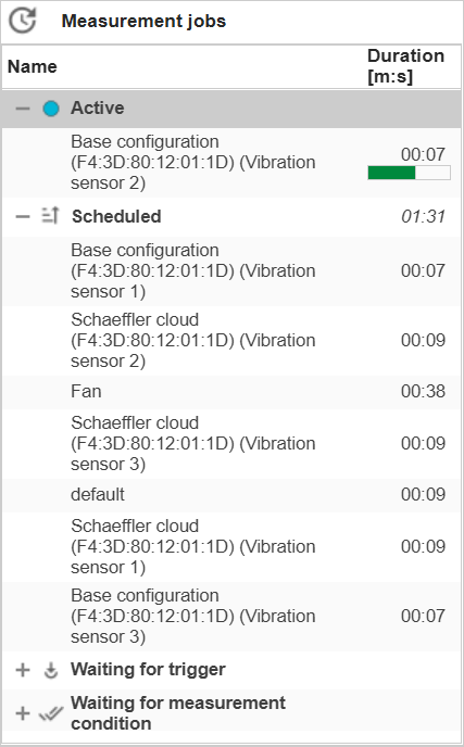
Instead of calculating the measurement time manually, you can also see the measurement time directly in SmartWeb in the
upper right corner of the status page for all measurement jobs:
I have an instable measurement condition or measurement trigger. How does the ProLink react to that?
A measurement condition can be used to enable measurement jobs only under certain conditions. For example, you can set a
measurement condition to only enable a measurement job when the machine is running in a certain speed range. With a
measurement trigger, you can start a measurement when a certain event occurs, for example when the speed exceeds a
defined value. While this sounds straightforward, in practice the machine’s operating conditions can be instable. For
example, the machine might be running in the defined speed range but with a lot of fluctuations.
When a measurement condition or trigger becomes instable, i.e. switching between valid and invalid very rapidly, this
would start measurements which would be cancelled right afterward due to the condition becoming invalid. To the user,
it might not be clear why no measurement is stored. Additionally, in the trend of the measurement condition and trigger,
there would be many alarm state changes that would only be visible when zooming the time period as they are so close to
each other. This could make it hard to read the trend and understand the machine’s operating conditions.
To prevent this, ProLink will detect an instable measurement condition or trigger and disable it until it becomes stable
again. Both the beginning and ending of the detected instability will be written to the logbook and be visible with a
gray background in the measurement condition’s or trigger’s trend.
Is it possible to switch between Hz and order?
When the turning speed is measured in a measurement job, the user can choose between Hz and orders in the SmartUtility
Viewer and in the ExpertViewer. In SmartWeb, this is only possible for measurements with activated order analysis.
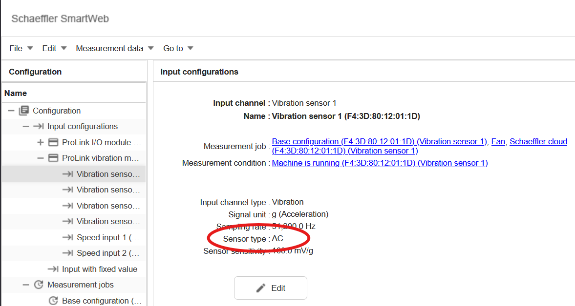
The signal of my vibration sensor looks like static noise. What can I do?
If the signal of your IEPE vibration sensor looks like static noise, it could be that the supply current of the sensor
is not activated. Please check if the input settings of the vibration input are set to “IEPE” and not to “AC” or “DC”.
See the manual for more information.
What is the minimum interval between two trend points?
The minimum interval between two trend points depends on several factors, like the duration of the measurement jobs and
the number of measurement jobs. The device will measure each measurement job after the other, with a waiting time of
5 seconds after each job. When there is only one measurement job, and the job is configured to store trend values
as often as possible, you can get down to a minimum interval of around 7 seconds between two trend points when using the
base measurement job.
Which roller bearings can I monitor with ProLink? Is there a bearing database?
The ProLink can monitor a wide range of roller bearings from any manufacturer. It has a bearing database which already
includes all roller bearings from Schaeffler, including the brands FAG and INA. Unfortunately, Schaeffler is not allowed
to provide bearing data of other manufacturers because of legal restrictions.
But bearings of any manufactured can be added manually, via Settings –> Bearings. Here you can enter a new bearing
with its kinematic frequencies, which usually can be found in the datasheet provided by the manufacturer. Another way
is to calculate these from the mechanical data of the bearing. A calculator for this is also included in the window
when entering a new bearing.
Which type of measurement job do I use for my machine?
ProLink provides templates for measurement jobs which are defined to suit different types of machines and
applications. Choosing the right measurement job type is crucial for accurate data collection and analysis. Here is the
list of our measurement job templates and their recommended use cases:
Template
Application
Base configuration
Broadband monitoring without specific component view.
Belt drive
Monitoring of belt drives.
Channel monitoring
Up to 3 channels monitored permanently (independent of other measurement jobs) with direct alarming.
Condition guard
Permanent monitoring of a vibration channel (independent of other measurement jobs) similar to the ISO10816 standard.
Coupling
Monitoring a coupling.
Default configuration
Similar to the base configuration, with some additional KPIs to find special statistical anomalies.
Fan
Monitoring of a fan.
Gear stage
Monitoring of a gear stage.
Journal bearing
Monitoring of a journal bearing.
Load duration distribution (LDD)
Classification of up to 2 channels to see in which operating conditions the machine is running over time.
Machine analysis essentials
Measures all the essential signals which are needed for an expert to do a manual analysis of the machine.
Process signal monitoring
Simple monitoring of up to 8 arbitrary signals, usually slow process signals.
Pump
Monitoring of a pump.
Rainflow counting (RFC)
Similar to LDD, but focussing on the change of the operating conditions rather than just the conditions themselves.
Roller bearing
Monitoring of a roller bearing
Schaeffler cloud services
Emulation of an OPTIME vibration sensor, providing the same KPIs as this sensor.
Shaft
Monitoring of a shaft.
Time synchronous averaging (experimental)
Experimental job to test time synchronous averaging.
Tracked frequency bands
User-defined frequency bands, which are moved calculated using the current speed of the machine.
User-defined frequency bands
Fixed user-defined frequency bands
Which types of components, machines and applications can ProLink monitor?
With ProLink, you can monitor all sorts of mechanical components like bearings, gears, fans, pumps, belt drives, etc.
The device comes with a configuration assistant, which already includes templates for most components. This makes it
very easy to configure the measurement configuration for a specific component, since the wizard will ask you all the
necessary questions and set up the measurement parameters accordingly.
The ProLink can monitor not only static machines. It can be set up to monitor machines with variable speeds and loads
as well. Also special applications, for example machines which only run for a short time and then stay idle for a long
time, are no problem. With the right input signals and configuration, ProLink can handle these applications as well.
Which types of measurement jobs can I use with OPTIME?
When onboarding ProLink with the SCOF file (Schaeffler Cloud Onboarding File), Schaeffler Cloud Services measurement
jobs are automatically created. After that, you can add more measurement job types to send their data to the OPTIME
cloud. This is done in the communication channel settings for the Schaeffler cloud in SmartWeb. The following additional
job types can be added:
Base configuration
Fan
Gear stage
Machine analysis essentials
Pump
Roller bearing
To analyse data from these addition job types on OPTIME side, the ExpertViewer is required. Here you can view the KPI
data and the time signals. Other than the cloud services jobs, no trend and time signal data is shown in the OPTIME
mobile app or OPTIME dashboard. However, you can see the alarm information in the OPTIME dashboard in the notification
list under the machine view, and in the IoT Ticket site asset tree under the telemetry data assets in the measuring
point.
Within which speed range can ProLink be used?
This depends on the application and the specific use case. In general, ProLink can be used for a wide range of speeds,
typically between 50 and 15,000 revolutions per minute (RPM).
 More information about configuring speed dependent alarm limits can be found in the