Can I install a ProLink module away of the cabinet?
The internal ProLink communication between each module is done with standard ethernet cables. The uplink cable has to be
able to transfer at least 100Mb/s. The maximum cable length is 100 meters. So yes: it is possible to install a ProLink
module away from the cabinet.
Doing so can reduce the cabling cost, since this allows the user to install the ProLink module close to the position of
the sensors, which can be far away from the cabinet.
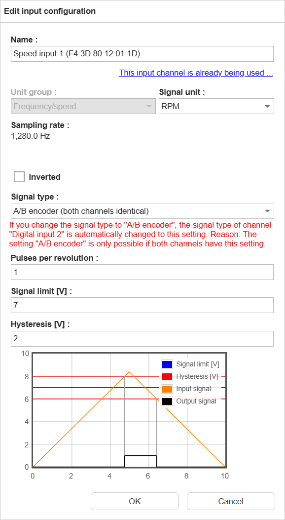
Can I measure the digital speed signal with directional information (A/B-encoding)?
Yes, this is possible with the digital inputs of the vibration module. Both the A and B signals must be connected to the
same module. The direction of rotation is determined by the phase shift between the A and B signals. If the A signal
leads the B signal, the rotation is in one direction, and if the B signal leads the A signal, the rotation is in the
opposite direction. This allows for accurate speed measurement with directional information.
In SmartWeb, edit the input configuration of one of the digital inputs and set the signal type to “A/B encoder (both
channels identical)”. After that, the user can select either of the two speed channels for the measurement
configurations, both will provide the same speed value, with the correct direction information. More information on the
other settings of the digital inputs can be found in the manual.
Can I use a combined sensor to measure both vibration and temperature with the ProLink?
Yes, you can use a combined sensor to measure both vibration and temperature with the ProLink. Directly connect the
vibration signal to an input of the vibration module. For the temperature signal, you can use either another input of
the vibration module or an input of the I/O module.
Can I use a network switch to connect ProLink modules?
The ProLink modules are connected via Ethernet, using the internal network switch in each module. However, there might
be situations where you want to use an external network switch to connect multiple modules together, e.g. when the
modules are far apart. This switch must support the precision time protocol (PTP, IEEE 1588v2).
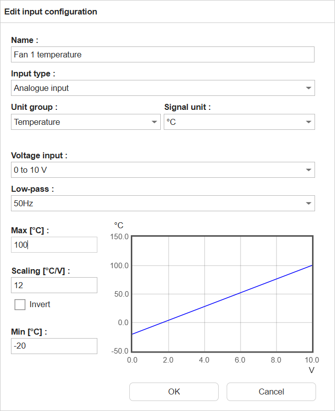
Can I use an analogue input of the vibration module for signals other than vibration?
Yes, you can connect any voltage signal to an analogue input of the vibration module, as long as the signal is within
the voltage range of the input (±10V). To use an analogue input for a non-vibration signal, you will need to change the
input type from “Vibration input” to “Analogue input” and change the unit group from “Vibration” to the appropriate unit
group for your signal (e.g. “Temperature”, “Pressure”, etc.). Then set the voltage input and min/max values according to
the sensor’s output range.
Can I use the network cable to power the ProLink?
No, ProLink does not support Power over Ethernet (PoE) according to the IEEE 802.3af Mode A standard. The use of a
separate power supply is required to power the device, and the Ethernet cable is only used for data transmission.
Do I have to connect the modules in a specific order in the ProLink cabinet?
The modules of ProLink can be connected in any position and in any order. The order in the cabinet might not match the
order of the modules in SmartWeb, but this does not affect the functionality. In SmartWeb, the modules are ordered
alphabetically by their names, which are by default the serial numbers / MAC addresses of the modules. You can change the name
of the modules in SmartWeb.
Do I have to use the digital speed input on the same module as the vibration inputs?
No, you can use any speed signal for a measurement job, from the same module as the vibration inputs or from a different
vibration module.
How can I check the sensor cabling?
Measure the voltage between the two sensor wires. Below 8VDC, it might be mis-polarity, below 1VDC a shortcut and above
20VDC an open wire.
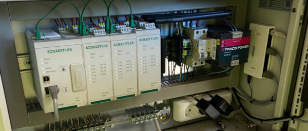
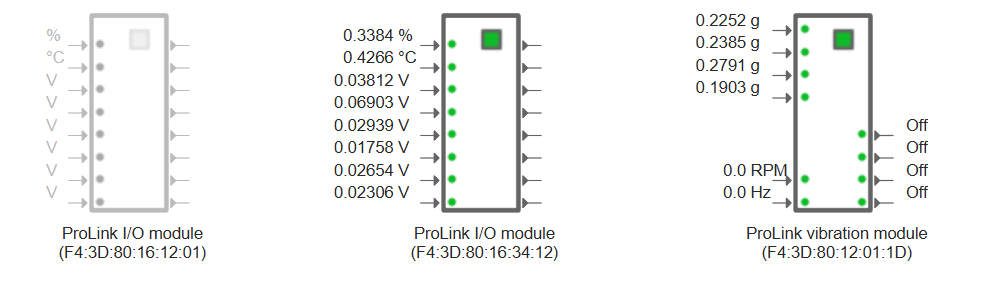
How can I find out which of my modules in the cabinet is which module in SmartWeb?
When you have multiple modules installed in your ProLink cabinet it can be difficult to identify which physical module
corresponds to which module in the SmartWeb interface. You can look at the serial number of each module (printed on the
label on the side), but this can be difficult or impossible when the modules are installed in a cabinet or rack.
To help with this, each module has an “identify” function that you can use to make the module’s I/O LEDs blink, making
it easy to locate. To do this, click on the green square of the module you want to identify in the SmartWeb interface
(on the status screen or the input or output configuration screen). This will start the “identify”-mode.
When a module has to be replaced, for example because it is defective, the following procedure has to be followed to
ensure that the measurement jobs will continue to work as before the replacement, i.e. the assigned inputs and outputs
in the measurement job are not changed.
Beware: you cannot exchange a module without losing the measurement data on the device.
Download configuration and measurement data via SmartWeb or SmartUtility to have a backup of the current
configuration
Power off the ProLink device
Disconnect all cables connected to the module to be replaced, build in the new module and reconnect all cables
Power on the ProLink device
Wait for the SmartWeb to be loaded and both the old (greyed out) and the new module (normal) are displayed on the
status page
Reload the SmartWeb page, since the automatic refresh might not have detected the new module
Delete the greyed-out module (Configuration -> Input configurations -> Select the greyed out module -> Delete)
Replay the previously downloaded configuration via SmartWeb or SmartUtility
Replace 2 modules at once:
In this case the software has to decide, which new module will replace which old module. In this case the new module
with the lower serial number will replace the module with the alphabetically lower module name (or serial number if
the name was not changed)
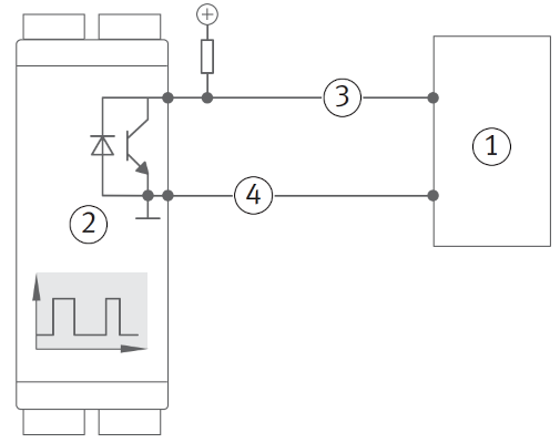
How do I connect a digital output (open collector)?
The digital output of the ProLink device is an open collector. This means that it can only pull the output to ground
(0V) and cannot provide a positive voltage. To connect a digital input, you will need to use a pull-up resistor, i.e. a
resistor that pulls the output to a positive voltage (e.g. 5V or 24V). The value of the pull-up resistor can be between
1kΩ and 10kΩ, depending on the input impedance of the device you are connecting to.
PLC
ProLink
Signal
Ground
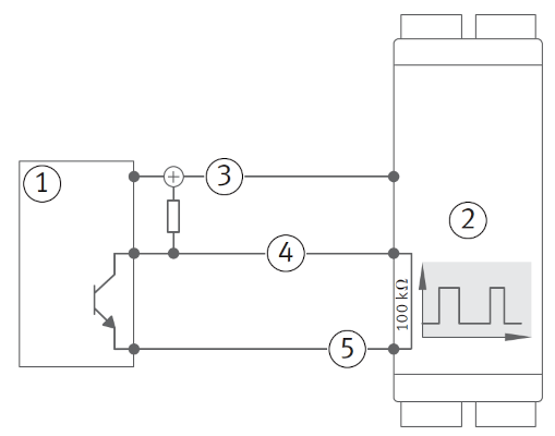
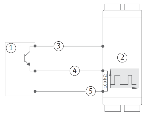
How do I connect a digital sensor to ProLink?
In general, there are two types of digital sensors: NPN and PNP. The main difference between the two is the way they
switch the output signal. NPN sensors switch the output signal to ground (0V), while PNP sensors switch the output
signal to a positive voltage (e.g. 5V or 24V).
When using a sensor with an NPN output, an external pull-up resistor is needed, which pulls the output to a positive
voltage. For this, the supply voltage for the sensor can be used. When using a sensor with a PNP output, no pull-up
resistor is needed, since the sensor itself switches the output to a positive voltage. The digital input of ProLink
already has an internal pull-down resistor, which pulls the output to ground when the sensor is not active.
NPN
PNP
PLC or sensor with an NPN output
ProLink
24V
Signal
Ground
PLC or sensor with an PNP output
ProLink
24V
Signal
Ground
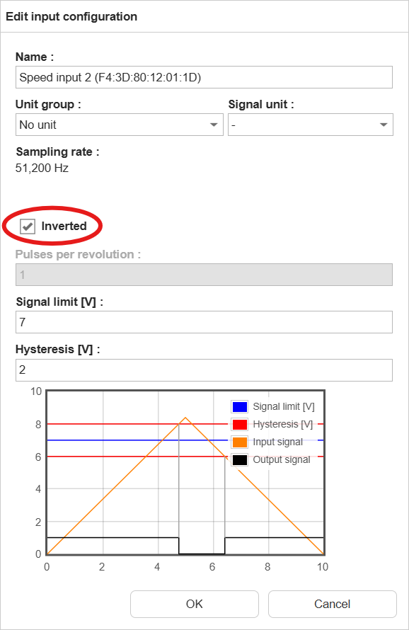
When using an NPN sensor, we advise to invert the input logic in the configuration of ProLink, so that a closed switch
corresponds to a high signal and an open switch corresponds to a low signal. This makes it easier to understand the
signal and to set up the monitoring configuration.
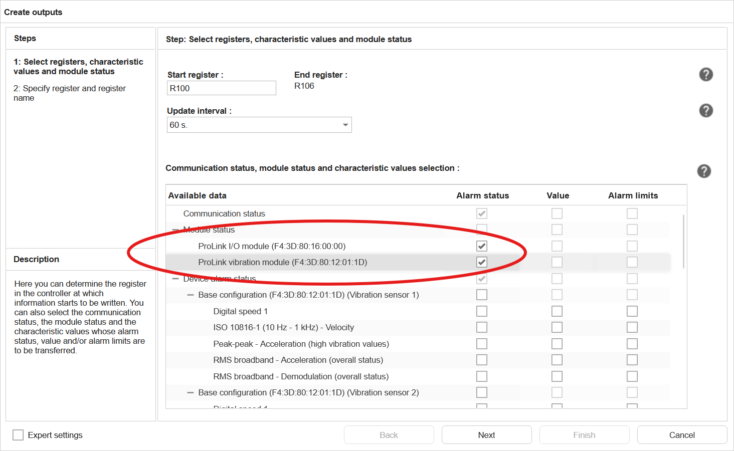
How do I interpret the status words used in external channels?
As user, you can add the (alarm) status of measurement jobs and characteristic values to the output of an external
fieldbus channel (SLMP, EtherNet/IP, PROFINET). As of firmware version 3.4.0, it is also possible to add the status of
the modules (including sensor state) as an output to the external channels of the device.
Measurement job and characteristic value status word:
The status words for the measurement jobs and characteristic values are 16-bit values, with the following values:
Alarm state value
Meaning
0
undefined
1
no alarm
2
pre alarm
3
main alarm
4
error
Module’s status
The module status words are 32-bit values, where some of the bits represent a specific status or condition.
Vibration module status word:
Bit position
31 (MSB)
30-10
9
8
7
6
5
4
3
2
1
0 (LSB)
Meaning
MS
-
DO4
DO3
DO2
DO1
DI2
DI1
AI4
AI3
AI2
AI1
Abbreviation
Meaning
Values
MS
Module Status
0: OK; 1: error
DO1-4
Digital Output 1-4
0: OK; 1: error (e.g short circuit of the output)
DI1-2
Digital Input 1-2
0: OK; 1: error
AI1-4
Analog Input 1-4
0: OK; 1: error (e.g. IEPE sensor error)
I/O module status word:
Bit position
31 (MSB)
30-8
7
6
5
4
3
2
1
0 (LSB)
Meaning
MS
-
IO8
IO7
IO6
IO5
IO4
IO3
IO2
IO1
Abbreviation
Meaning
Values
MS
Module Status
0: OK; 1: error
IO1-8
Input/output channel 1-8
0: OK; 1: error (e.g. undercurrent in a 4-20mA loop)
How do I measure temperature with the ProLink?
There are several ways to measure temperature with the ProLink, depending on the type of temperature sensor you want to
use. The ProLink supports the following types of temperature sensors:
Sensor / signal
Vibration module
I/O module
Pt100 / Pt1000
-
✓
Voltage output
✓
✓
Current output
-
✓
Vibration module
When using an input of the vibration module to measure temperature, the following steps are needed:
Check if the input is already in use by a measurement job, measurement trigger or measurement condition. If this is
the case, you will need to change the measurement job, trigger or condition to use a different input.
Change the input type from “Vibration input” to “Analogue input”.
Change the unit group from “Vibration” to “Temperature”.
Set the low-pass to 50Hz.
Set the voltage input and min/max values according to the temperature sensor’s output range.
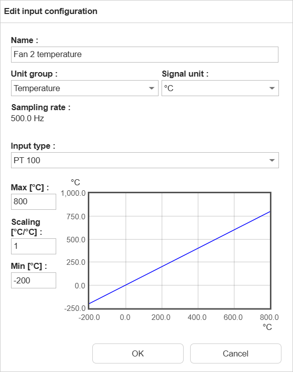
Pt100 / Pt1000 sensors
First check if the I/O channel is set to “Analogue input”. If this is not the case, you will need to change the I/O
channel type to “Analogue input” by selecting the I/O module in the input configuration screen and click “Edit”.Then set
the unit group to “Temperature” and then set the input type to Pt100 or Pt1000. Then set the correct temperature range
for the connected sensor.
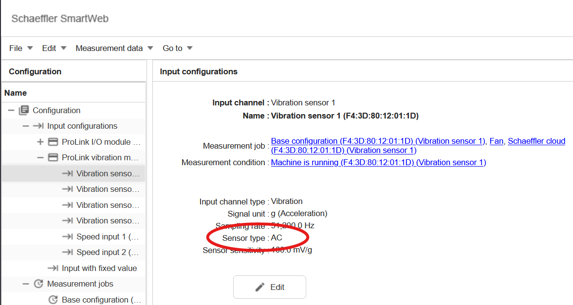
The signal of my vibration sensor looks like static noise. What can I do?
If the signal of your IEPE vibration sensor looks like static noise, it could be that the supply current of the sensor
is not activated. Please check if the input settings of the vibration input are set to “IEPE” and not to “AC” or “DC”.
See the manual for more information.
What is the maximum cable length for the vibration sensor on the machine?
We recommend a cable length of up to 50m for acceleration sensors. It depends on the quality of the cable, e.g. the
shielding, and on the environment, e.g. the electromagnetic interference. If cables are longer, the risk of distortions
on the cable and therefore on the sensor’s signal is higher.
What kind of acceleration sensors can be used?
ProLink supports IEPE (Integrated Electronics Piezo-Electric) acceleration sensors. In the software you can configure
settings like the sensitivity and the bias voltage range.
Which setting do I use for the inputs of the vibration module?
When configuring the inputs of the vibration module, you can choose from 3 options:
IEPE: use this when you have an IEPE sensor, i.e. a sensor that needs a constant current supply.
AC: use this when you have a signal that is already conditioned, e.g. from a charge amplifier or an integrated sensor
with built-in signal conditioning, or an output from a PLC. AC means, that any DC offset is removed from the signal,
so you only measure the alternating part of the signal.
DC: use this when you have a signal that is already conditioned, e.g. from a charge amplifier or an integrated sensor
with built-in signal conditioning, or an output from a PLC. DC means, that you measure the full signal including any
DC offset. DC is typically used for signals which only change very slowly, or where the absolute value is needed,
like temperature or speed.
When selecting IEPE, the current supply for the sensor is activated. Make sure to only use IEPE sensors on these inputs,
as other sensors might be damaged by the constant current supply. This also activates the monitoring of the sensor’s
supply voltage, which is used to detect cable issues or a disconnected sensor. The allowed voltage range, which is
different for each sensor (type), can be defined in the input settings under min/max bias voltage (see
manual, vibration module dialogue). When the voltage on the sensor cable is below this
value, then there is a short-circuit in the sensor or cable. Is it above, then the cable is broken or no sensor is
connected (open loop). When no signal or sensor is connected to the input, selecting IEPE will always show the input /
sensor as defective.
When selecting AC or DC, no current supply is activated. These settings can be used with any sensor or signal source.
Which type of network cable should I use to connect the modules?
We supply short network cables for the connections between the modules. However, if you need to use longer cables, you
can use standard Ethernet cables (Cat5e or higher).
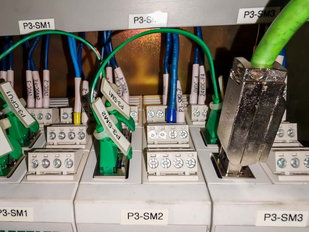
Important: Please use flexible network cables rather than rigid or sturdy cables. Stiff cables can put mechanical
strain on the network sockets of the modules, potentially causing damage over time. Flexible cables help prevent stress
on the connectors and ensure reliable connections.
For example, do not use stiff industrial cables with big network connectors, as these are too rigid and will apply
excessive mechanical stress to the module sockets. The following picture shows an example of an otherwise very
good-looking installation. As you can see, the network socket is bent and damaged due to the use of a stiff cable.