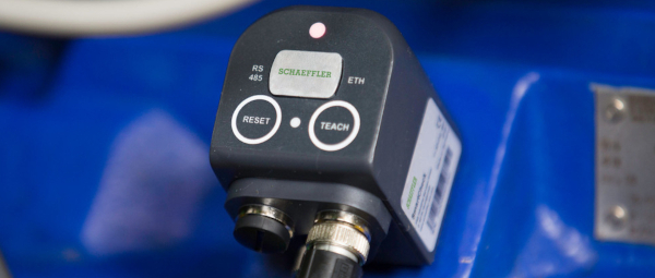
Can I use the network cable to power the SmartCheck?
Yes, SmartCheck supports Power over Ethernet (PoE) according to the IEEE 802.3af Mode A standard. This allows the device
to receive both data and electrical power through a single Ethernet cable, simplifying installation and reducing the
need for additional power sources.
Do the M12 plug connectors on SmartCheck have a special coding?
No, they are standard M12 plug connectors. Only the M12 ethernet cable has a D coding.
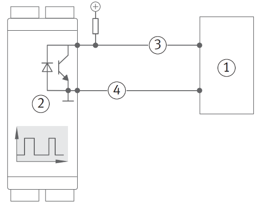
How do I connect a digital output (open collector)?
The digital output of the SmartCheck device is an open collector. This means that it can only pull the output to ground
(0V) and cannot provide a positive voltage. To connect a digital input, you will need to use a pull-up resistor, i.e. a
resistor that pulls the output to a positive voltage (e.g. 5V or 24V). The value of the pull-up resistor can be between
1kΩ and 10kΩ, depending on the input impedance of the device you are connecting to.
PLC
SmartCheck
Signal
Ground
How do I connect a digital sensor to SmartCheck?
In general, there are two types of digital sensors: NPN and PNP. The main difference between the two is the way they
switch the output signal. NPN sensors switch the output signal to ground (0V), while PNP sensors switch the output
signal to a positive voltage (e.g. 5V or 24V).
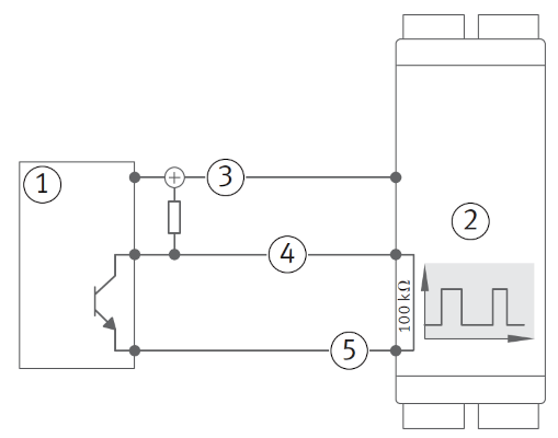
When using a sensor with an NPN output, an external pull-up resistor is needed, which pulls the output to a positive
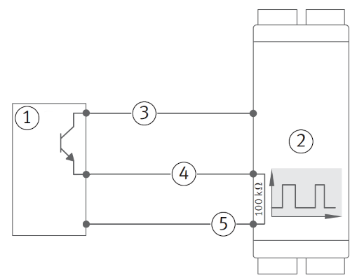
voltage. For this, the supply voltage for the sensor can be used. When using a sensor with a PNP output, no pull-up
resistor is needed, since the sensor itself switches the output to a positive voltage. The digital input of SmartCheck
already has an internal pull-down resistor, which pulls the output to ground when the sensor is not active.
NPN
PNP
PLC or sensor with an NPN output
SmartCheck
24V
Signal
Ground
PLC or sensor with an PNP output
SmartCheck
24V
Signal
Ground
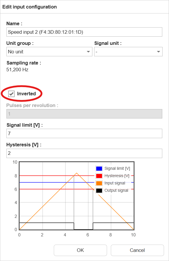
When using an NPN sensor, we advise to invert the input logic in the configuration of SmartCheck, so that a closed switch
corresponds to a high signal and an open switch corresponds to a low signal. This makes it easier to understand the
signal and to set up the monitoring configuration.
How do I interpret the status words used in external channels?
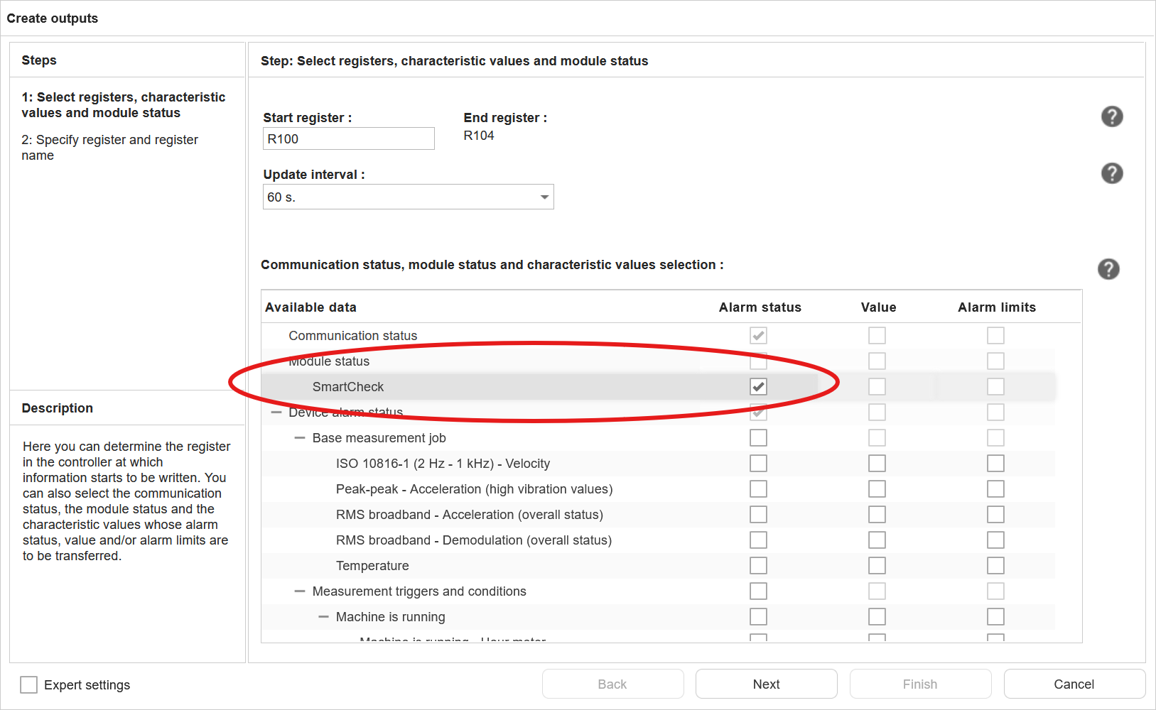
As user, you can add the (alarm) status of measurement jobs and characteristic values to the output of external
fieldbus channel (SLMP).
Measurement job and characteristic value status word:
The status words for the measurement jobs and characteristic values are 16-bit values, with the following values:
Alarm state value
Meaning
0
undefined
1
no alarm
2
pre alarm
3
main alarm
4
error
SmartCheck status
The SmartCheck status word is a 32-bit value, where some of the bits represent a specific status or condition.
Bit position
31 (MSB)
30-7
6
5
4
3
2
1
0 (LSB)
Meaning
MS
-
DO
AO
DI
AI2
AI1
T
V
Abbreviation
Meaning
Values
MS
Module Status
0: OK; 1: error
DO
Digital output status
0: OK; 1: error
AO
Analogue output status
0: OK; 1: error
DI
Digital input status
0: OK; 1: error
AI1-2
Analogue input status
0: OK; 1: error
T
Temperature sensor status
0: OK; 1: error
V
Vibration sensor status
0: OK; 1: error
How do I measure temperature with the SmartCheck?
There are several ways to measure temperature with the SmartCheck, depending on the type of temperature sensor you want to
use. The SmartCheck supports the following types of temperature sensors:
Sensor / signal
SmartCheck
Pt100 / Pt1000
-
Voltage output
✓
Current output
✓
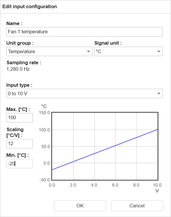
When using one of the analogue inputs of SmartCheck to measure temperature, the following steps are needed:
Check if the input is already in use by a measurement job, measurement trigger or measurement condition. If this is
the case, you will need to change the measurement job, trigger or condition to use a different input.
Change the unit group to “Temperature”
Set the input type and min/max values according to the temperature sensor’s output range